
 So, you’ve been asked to purchase or repair an air compressor for your facility. You know, that noisy square box in the corner with the pipe connected to it. The box that everyone ignores until it stops running! Ever wondered what is actually going on inside that mysterious box to make it so important? While there are several different compressor technologies available, for the purpose of this discussion we will address the most common design which is an oil flooded rotary screw compressor.
Why do we need a compressor?
Compressed air is used in every manufacturing plant to power pneumatic tools, production equipment, air cylinders, instrumentation, sandblasting and painting, to name just a few of the millions of applications. Most everyone is familiar with pulling up to a roadside air hose and inflating a car or truck tire. We all know that somehow a high-pressure flow of compressed air comes out of that hose. If we connect this air flow to a pipe and run enough of it throughout our plant, we can now power the applications such as those mentioned above.
How does the Magic Happen?
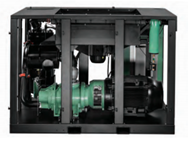
 Our discussion will revolve primarily around the oil flooded rotary screw compressor. These machines are typically available from very small 5 Horsepower units all the way up to 600 + Horsepower for large plant air installations. Regardless of the size, the technology and theory of operation is the same.
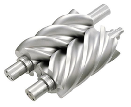
The “heart” of the package is the rotary screw “air end” unit. In simple terms, the air end uses a male and a female rotor that meshes together to “smash” the incoming 14.5 psia atmospheric air. As these rotors turn, the pressure of the air increases to a final discharge pressure that can be sent down the pipe to the system. In simple terms, think of the male rotor as the piston and the female rotor as the cylinder. As these rotate and mesh together, the end result is a smooth, constant delivery of compressed air at the discharge end of the air end.
The Heat is On!
During the process, lubricating fluid is injected into the compression area for lubricating the bearings, cooling and removal of the heat of compression, and sealing of the passages between the rotors as well as between the rotors and outside housing. The lubricating fluid absorbs the heat of compression as it circulates through the system. As this lubricant is continuously flowing through the system, the heat must also be continuously removed. This is done by flowing the hot oil through an air-cooled radiator type cooler with a cooling fan, or through a water-cooled shell and tube heat exchanger. Once cooled, the lubricant is sent back to the system and the process starts over again.
It’s All About Control:
Ok, now that we are compressing air and cooling the lubricant, how do we automatically control the amount of compressed air we deliver as well as the final discharge pressure? The most basic controls involve manipulating the amount of air that passes through the compressor inlet. This has a direct effect on the amount of compressed air that passes through the machine and ultimately out into the discharge pipe. The following are the basic control modes commonly used for oil flooded, rotary screw compressors.
1) Load / Unload: In this scenario a compressed air signal tells the compressor inlet to be either fully open or fully closed. This air signal is based on sensing the discharge pressure downstream. In this type of control, the compressor is either delivering its full flow or zero flow based on this air signal. This type of control results in pressure fluctuations downstream and requires a significant amount of compressed air storage (air tanks) to make the system operate efficiently.
2) Inlet Modulation: In this scheme the compressor inlet valve modulates or is constantly regulated by an air signal. This allows the inlet valve to react quickly to changes in the downstream pressure and maintain a more constant downstream discharge pressure without the pressure fluctuations of the Load / Unload control. This works very well across the operating range of the compressor. However, it is very inefficient from a power perspective. When operating under modulating controls, a rotary screw compressor will typically be pulling at or near full power regardless of its output. This results in excessive power consumption during periods of lower air demand.
3) Variable Displacement: A couple of manufacturers build compressors with internal air end unloading capabilities. In the Sullair Spiral Valve control set up, openings are machined into the air end that basically reduce the usable length of the air end resulting in more efficient operation at lower flows. The compressed air flow is varied by opening or closing these machined slots based on the downstream pressure. This system is very efficient down to approximately 50% flow. This is a very cost-effective way to achieve better efficiencies without a significant amount of added capital expense.
4) Variable Speed Drive: The most efficient control is the use of a variable speed drive to vary the speed of the motor based on the downstream system pressure. The variable speed allows the compressor to operate across almost the entire operating range 15% to 100% of the compressor’s capabilities. While this design provides the highest efficiency across the range, it is also significantly more expensive than compressors with the other control designs.
In summary, the oil flooded, rotary screw compressor is the most widely used type of compressor for a large majority of manufacturing plants. Whether you have the personnel to maintain your compressors “in house”, or whether you rely on one of several Blake & Pendleton, Inc. maintenance plans, when properly maintained, these compressors can provide many years of reliable service. The key factors are changing the filters and fluids on a strict schedule, performing routine fluid analysis, taking action before a situation becomes a problem, and keeping an eye on the control components.
Contact your Blake & Pendleton Area Manager to discuss our maintenance plan options or to learn more!